15 Results
View results:
Sort by:
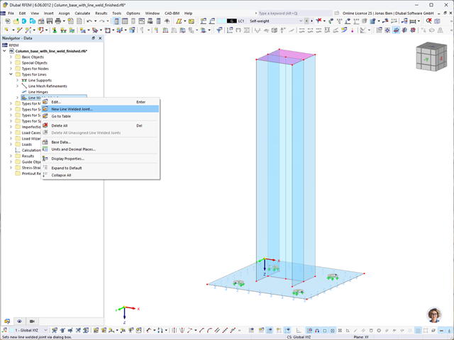
In RFEM 6, it is possible to define line welds between surfaces and calculate the weld stresses using the Stress-Strain Analysis add-on. This article will show you how to do it.

Steel connections in RFEM 6 are defined as an assembly of components. In the new Steel Joints add-on, universally applicable basic components (plates, welds, auxiliary planes) are available for entering complex connection situations. The methods with which connections can be defined are considered in two previous Knowledge Base articles: “A Novel Approach to Designing Steel Joints in RFEM 6" and “Defining Steel Joint Components Using the Library".

The RF‑/STEEL EC3 add-on module can perform the design of fillet welds for all parametric, welded cross-sections of the cross-section library. For this, the option must be activated in the detail settings of the module. As an alternative, you can also use a surface model for the design.
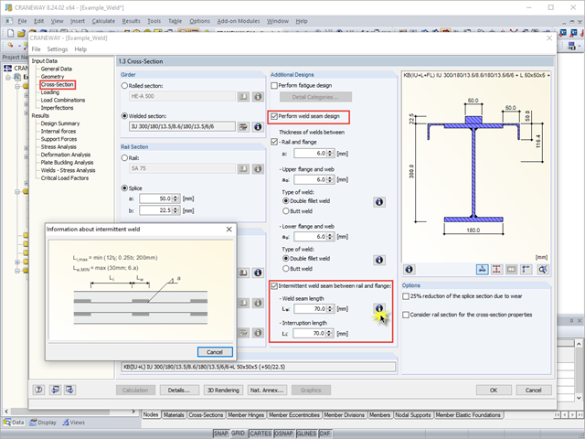
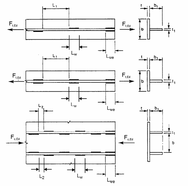
When using interrupted welds between the rail and flange, make sure that the applied weld length does not exceed the length of the rigid load application of the wheel load according to Equation 6.1 in [1].

The European standard EN 1993-1-8, Section 4.5.3.3. provides the user with a simplified method for the ultimate limit state design of fillet welds. According to the standard, the design is fulfilled if the design value of the resultant acting on the fillet weld area is smaller than the design value of the weld's load-bearing capacity. Thus, if you want to dimension the weld for a surface model, you will be faced with a variety of results due to the nature of FEM calculations. Therefore, we show in the following text how to determine the force components from the model.

A welded connection of an HEA cross-section under biaxial bending with axial force will be designed. The design of welds for the given internal forces according to the simplified method (DIN EN 1993-1-8, Clause 4.5.3.3) by means of SHAPE-THIN will be performed.
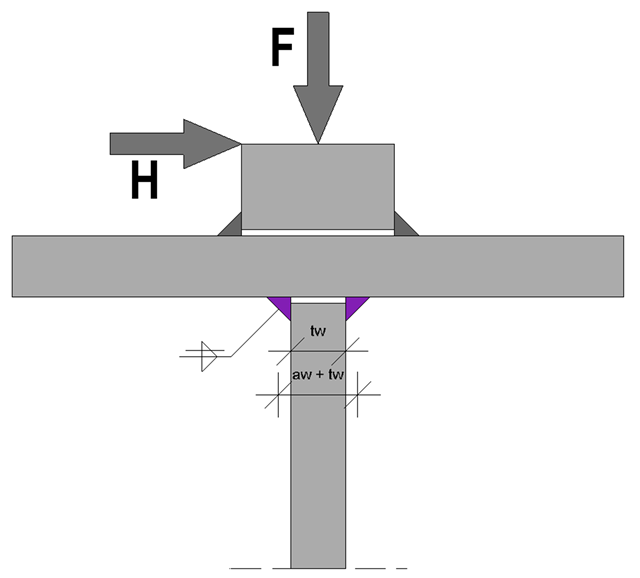
At the end of the topic on the design of welds on runway beams - after the technical articles about the rail weld seam in the ultimate limit state and the limit state of fatigue - a technical article about web fillet welds now follows. Both the ultimate limit state and the fatigue limit state are considered.

A fillet weld is the most common weld type in steel building construction. According to EN 1993-1-8, 4.3.2.1 (1) [1], fillet welds may be used for connecting structural part where the fusion faces form an angle of between 60° and 120°.
Based on the technical article about the ultimate limit state design of rail welds, the following explanation refers to the process of fatigue design of rail welds. In particular, this article explains in detail the effects of considering an eccentric wheel load of 1/4 of the rail head width.
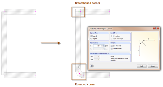
With the SHAPE-THIN cross-section program, you can model the corner areas of cross-sections in detail: The "Smooth Corner" function fills the corner with an element and automatically connects it with a null element. For this, simply click the corner. Use the "Create Round or Angled Corner" function to round or angle the corner. To do this, specify the fillet radius and click both elements.
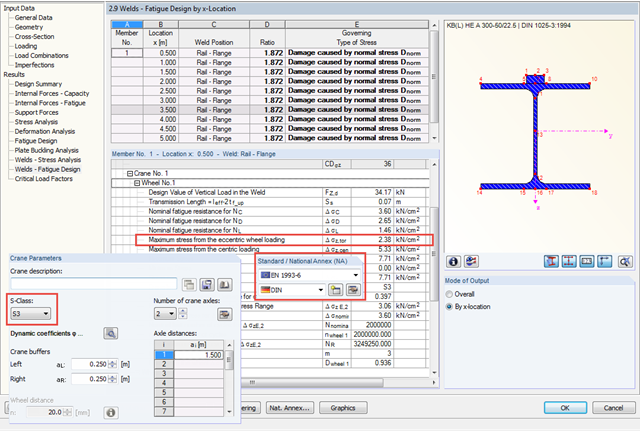
In CRANEWAY, the eccentric wheel loading of 1/4 of the rail head width is used for the fatigue design of welds as well as for craneway girder design according to the National Annex of Germany and as of damage class S3.
If crane runway girders are designed with flat steel rails, the welding of these rails is always a detail for the design. You can generally select between continuous and intermittent fillet welds as a rail fixing. The following article provides an overview of the design processes and their specific features, especially when using the EN 1993-6.

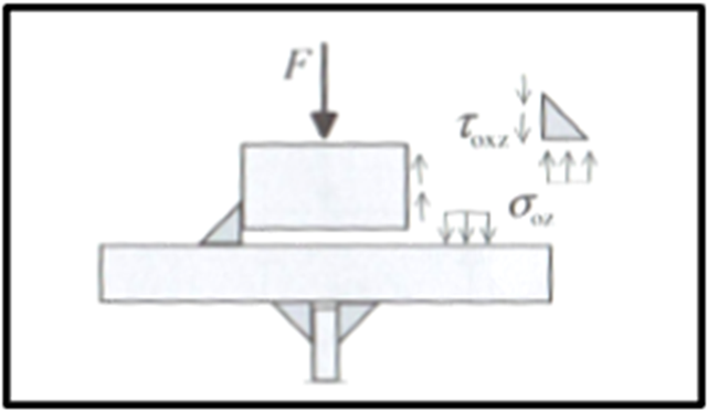
In RF-STEEL Surfaces, it is possible to display the stresses relevant for the design of welds, for example, according to EN 1993‑1‑8, Figure 4.5. When evaluating the stress components, the local xyz-axis system of the surfaces must be considered.
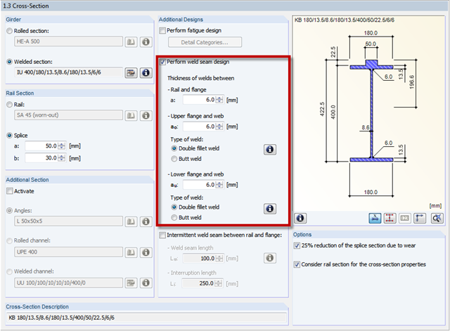
In CRANEWAY, the welds between the flanges and the web of a cross‑section are dimensioned. Options are available for defining the weld as a double fillet weld or a butt weld.
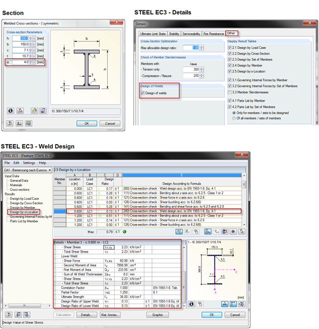
When using a welded profile, weld seam verification can also be carried out in RF-/STEEL EC3 as part of the design. The program performs the typical designs according to EN 1993‑1‑8.